I hope everyone has gotten off to a good start in the New Year. This month Iĺll be discussing the setup of standard F2D models, and how to
make sure they will hold up during test flying at matches. Next month, Iĺll discuss the multitude of trim adjustments you can make to get them
flying just to your liking.
The ready to fly F2D planes that you can buy these days are general built with very high quality. Over many years of experience and observation,
however, we have come up with a list of things you can do to avoid the occasional (sometimes catastrophic) mishap. First, always inspect the
covering very thoroughly over the entire model. Make sure that the edges are sealed well, and that there are no punctures. At high speed, the
wind rushing over even a small pinhole in the covering over one of the open bays is enough to start a rip thatĺll pull a large portion of the
covering off of your wing. When this happens, it happens quickly and without warning; depending on where this happens in your flight, it might
cause you to go straight into the ground. Preventing this from happening is quite simple though, since all that is required is a quick
inspection of the model for damage before each flight.
If you plan on flying any individual one of your models many times before taking it up in combat, there are also some other preventative measures
you can take with regard to the covering. Since combat models are designed with a finite, relatively short life expectancy in mind, they arenĺt
necessarily designed to hold up over 100ĺs of flights. As a result, sometimes the edges of the covering arenĺt sealed down real well, and may
start to come up after many flights. To head off this problem, you can seal down the covering at the center rib with a 1ö to 1.25ö wide strip
of Fascal on top and bottom. This will help join the covering of the inboard and outboard wings (they are separate pieces), and keep the
covering tighter for a longer period of time. Also, you should check the covering at the trailing edge. Some builders seal this connection
with tape already, while others donĺt. If your trailing edges arenĺt already sealed down with an extra strip of tape, I recommend going ahead
and doing this for yourself.
Now, youĺre ready to install the pushrod and tail (for non-sewn-hinge designs). Installing the pushrod is fairly self-explanatory, but the tail
has just a little more to it. There are two methods of installing the hinge pin, shown in the figure.
Usually, the hinge pins come with a
double bend as shown in the top part of the figure. The way this type of hinge pin is installed is just as shown, with some very sticky tape or
Fascal used to hold it in. It is also possible to re-bend the hinge pin for installation as shown in the bottom part of the figure. Here, a
very tight-fitting piece of rubber/silicone tubing is used on one end to prevent the pin from sliding one direction, while a 90o bend at the
other end holds the pin from sliding the other direction. In either case, the bent end should always be on the inboard side, so that the
centrifugal force will be helping to keep the pin in, rather than trying to cause it to fly out.
A common trinket for attaching the pushrod to the control horn is a little brass fitting with a screw, used ordinarily in electrical wiring
applications. You should start with this in the top hole of the control horn, and only move it down later if you feel like you need more
control. This is one of the most vulnerable parts of the model to failure, so you should treat it with a lot of respect. Iĺve seen these
come loose on people (including myself) many times in the past, so you need to always make sure itĺs tight before flying. Usually itĺs enough
just to give it a little ôsnugging-upö at the beginning of each flying session. One thing you always have to watch out for with these brass
fittings, however, is that they tend to develop cracks from over-tightening. Always inspect carefully for cracks, and if you see one starting,
throw the piece away and replace it. A way to circumvent this problem entirely is to throw away all those brass fittings from the start, and
replace them with the correct size wheel collar. When you find the correct size of wheel collar, youĺll notice that itĺs threaded for 4-40
bolts. Remove the set screw that it comes with and use a standard short 4-40 bolt in its place, and youĺre all set. Even with the wheel collars,
however, you still need to be sure to check that itĺs tight before each flying session.
The 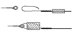 typical F2D lead-out ends are also probably different from what youĺre used to. The second figure shows how they work. You need to find
some silicone fuel tubing that will fit snugly over the lead-out ends. Cut two Żö long pieces of this tubing, and slide one over each lead-out.
Next, slide the loop/eyelet on the end of your line over each lead-out end hook, and pull the tubing back up onto the lead-out end. These
pieces of tubing will prevent the lines from slipping off during and between flights.
typical F2D lead-out ends are also probably different from what youĺre used to. The second figure shows how they work. You need to find
some silicone fuel tubing that will fit snugly over the lead-out ends. Cut two Żö long pieces of this tubing, and slide one over each lead-out.
Next, slide the loop/eyelet on the end of your line over each lead-out end hook, and pull the tubing back up onto the lead-out end. These
pieces of tubing will prevent the lines from slipping off during and between flights.
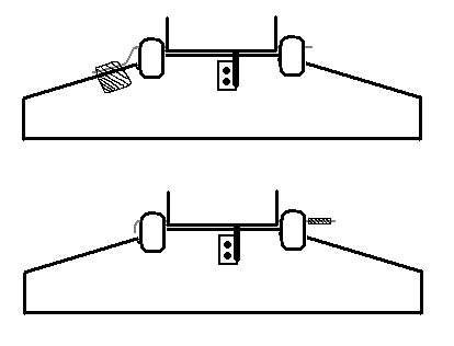
One last bit of prophylactic work you can do on your new models is to ensure that your bellcrank axles are securely glued in. Some builders
rely on a press-fit between the axle and the center-rib to keep the axel in place; often this is not enough, and the axle may simply fall out
during flight. As you might imagine, the consequences usually arenĺt too pretty. Usually, by feeling around with your fingers/looking carefully
in the light, you can see where the bellcrank axle comes up through the center rib. With a sharp x-acto knife, cut away a small square of
covering centered over the tip of the axle. Make the hole as small as possible, exposing just a very small area around the axle, being careful
not to extend the hole out to the edges of the wood center rib. There are several layers of covering here (usually one colored and two clear),
so be sure that youĺve removed all layers of film down to the bare wood/metal pin. A few drops of thin C/A glue are all thatĺs needed to secure
the pin in place. Cover over the hole with a patch of Fascal or other covering and repeat on the bottom side. It recently came to my attention
that many people are not aware of the fact that nitromethane attacks C/A glue. This means that any time you make a repair with C/A glue, you
need to be sure to cover over it because exposure to fuel residue will eventually dissolve your bond!