|
|
Welcome to the F2D News "How-To" Instructional Guide on: |
| Measuring and Setting an Engine's Head Clearance | ||||
|
|
Back | Page 1 of 3 | Next |
|
|
|
||||
| Introduction - Engine Basics | ||||
|
The figure to the right is a cartoon cut-away drawing of the inside of an F2D engine,
As the crankshaft rotates about its axis, the piston is forced to move up and down in the cylinder by the connecting rod. Because the piston and cylinder liner have a tight fit even at operating temperature, raising the piston causes whatever is above it in the combustion chamber to be compressed. By itself this process generates no power, but when there is a combustible mixture of fuel and air in the chamber the story becomes much more interesting. When the fuel/air mixture in the chamber is quickly compressed by the piston racing upwards, there is no time for heat to dissipate out of the chamber through the walls of the cylinder. As a result, both the pressure and temperature of the mixture are raised during the upward part of the stroke, bringing the mixture right to the edge of combustion. To achieve combustion and release the energy stored up in the chemical bonds of the fuel, however, one more bit of activation is needed; providing this activation is the role of the glow plug. Unlike the spark plugs in an automobile engine which need an external source of electricity to provide an ignition spark every second revolution
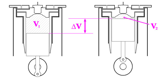
Additionally, the glow plug coil serves another purpose of which many people are unaware. It is no accident that, of all of the possible materials one could choose to make a heating coil, one of nature's most precious metals -- platinum -- is nearly universally used in glow plug coils. The reason is that platinum acts as a catalyst for combustion. A catalyst is a substance that increases the rate of a chemical reaction, without actually being consumed in the reaction. In effect, the glow plug not only provides the heat needed to bring the fuel/air mixture across the combustion threshold, but also lowers this threshold. Ideally, the fuel/air mixture will ignite from the top of the head chamber (by the glow plug coil) just as the piston comes to the top of its stroke. An advancing flame front propagates down through the combustion chamber, burning the remaining fuel/air mixture and causing further heating and expansion of the exhaust and other gases (nitrogen, carbon dioxide, still un-reacted fuel/oxygen mixture, etc.) in the chamber. The pressure from these expanding gases exerts a downward force on the top of the piston as it begins and carries out its downward stroke, supplying the necessary torque to turn the propeller and pull your model through the air. But what determines the strength of this force and the power output of an engine? While there are many factors involved such as fuel mixture, venturi size, case porting, etc., in this guide we will focus on those factors controlled by the piston/liner and head configuration. The figure below shows the three important quantities that will be the focus of our discussion.
The configuration on the left, with the piston all the way at the bottom of its stroke, is called Bottom Dead Center (BDC); the configuration on the right is likewise called Top Dead Center (TDC). The quantity DV is called the swept volume or displacement of the engine and is defined as the product of the stroke (the distance traveled by the top of the piston between TDC and BDC) and the bore (the projected area of the top of the piston). As you probably already know, the displacement plays a major role in determining the power-potential of an engine; in F2D, the displacement is regulated by a maximum value of 2.5 cc. In addition to the swept volume, there are two other important volumes V1 and V2 represented by the shaded areas in the figure. These volumes are the total combustion chamber (including the head chamber) volumes at BDC and TDC, respectively. Note that D V = V1 - V2. By taking the ratio V1/V2, we get an important number called the compression ratio of the engine, which quantifies how much the fuel/air mixture is compressed during each stroke. The higher the compression ratio is, the more vigorous the combustion reaction will be. However, setting the compression ratio to too high results in a detrimental effect on engine performance as will be discussed later. |
||||
| Next Page | ||||
|
|
||||
|
If you have any questions or comments, please email Mark at rudner@mit.edu |
||||
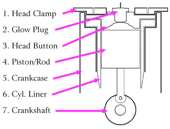 as viewed from the rear (i.e. through the backplate). For simplicity, ports in the case and liner that allow fuel, air, and exhaust in and out of
the combustion chamber are not shown. Variations on this diagram will be used throughout this guide, so take a moment to familiarize yourself
with the way each of the pieces is drawn here. The drawing is not intended to be accurate to any kind of scale, and is a fairly generic depiction
of the inside of any F2D engine. Note that a few engines, such as the Cyclon PC6, combine the head clamp (1) and head button (3) into a single piece.
as viewed from the rear (i.e. through the backplate). For simplicity, ports in the case and liner that allow fuel, air, and exhaust in and out of
the combustion chamber are not shown. Variations on this diagram will be used throughout this guide, so take a moment to familiarize yourself
with the way each of the pieces is drawn here. The drawing is not intended to be accurate to any kind of scale, and is a fairly generic depiction
of the inside of any F2D engine. Note that a few engines, such as the Cyclon PC6, combine the head clamp (1) and head button (3) into a single piece.
 of the crankshaft, a glow plug needs no external energy source to maintain the combustion cycle once it has started. Inside the glow plug, there is
a coil of platinum wire that is exposed to the combustion chamber at its highest point inside the head chamber. To start the engine an electric
current is run through the coil, which causes it to heat up and initiate the combustion process. Once the engine is running, however, the heat
generated by each cycle of the engine is enough to maintain the temperature of the coil and sustain the cycle.
of the crankshaft, a glow plug needs no external energy source to maintain the combustion cycle once it has started. Inside the glow plug, there is
a coil of platinum wire that is exposed to the combustion chamber at its highest point inside the head chamber. To start the engine an electric
current is run through the coil, which causes it to heat up and initiate the combustion process. Once the engine is running, however, the heat
generated by each cycle of the engine is enough to maintain the temperature of the coil and sustain the cycle.