|
|
Welcome to the F2D News "How-To" Instructional Guide on: |
| Measuring and Setting an Engine's Head Clearance | ||||
|
|
Back | Page 2 of 3 | Next |
|
|
|
||||
| Measuring the Head Clearance | ||||
|
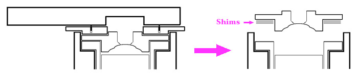
By inserting or removing shims from the space between the shelf of the head button and the flange of the liner, one can decrease or increase the compression ratio. Even if you are not worried about maximizing your engine's performance, it is still important to learn how to measure the head clearance. Running an engine with an extremely low (or even negative) head clearance can cause severe damage to the piston, liner, rod, and head. For this reason, it is always wise to check the head clearance of a new engine before its first run if you do not already know that it was set up by an experienced mechanic. Below is a list of steps that will walk you through checking your engine's head clearance. This can be done with the engine on or off the model, and can even be done on the field in under five minutes once you have the hang of it. Step 1: With the head tight, remove the glow plug using a 3/8" hex socket or box-end wrench.
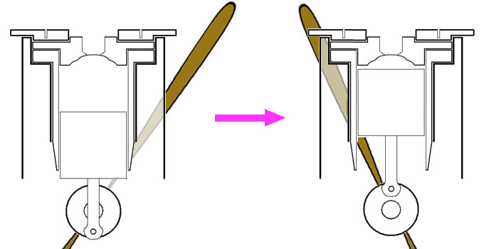
Step 2: With a propeller mounted on the engine, work the piston up and down to find the position of TDC, and leave the piston stuck at this position. The tight fit of the piston in the liner will keep it from leaving this position. If the engine is on a model, TDC can be found by feel. It will take a little time to gain confidence in your ability to find TDC in this manner. If the engine is not on a model, by removing the back plate you can look inside and use your eyes to see when the crank-pin reaches its apex. The fit between the piston and liner of a cold engine can be quite tight, making all of this a little tricky to carry out. Adding a few drops of oil to the cylinder may help.
This step is critical to ensure an accurate head clearance measurement. Failure to find TDC will always result in a larger than actual value for the measured head clearance. Step 3: Without bumping the propeller or otherwise disturbing the piston from its position at TDC, use your engine's head wrench to remove the head clamp. Next, gently remove the head button from the liner, making sure not to lose any shims in the process. With a very tight engine, the liner may pop up slightly when the head is removed. If this happens, it means that TDC was not found properly, and the head must be re-tightened and step 2 repeated. Remove any remaining shims from the flange of the liner and place them with the head.
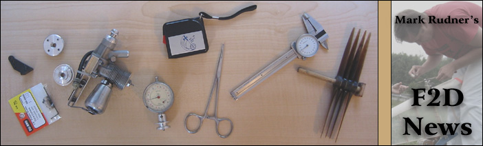
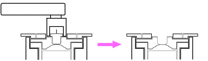
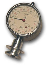
My personal instrument of choice is the Soviet-made dial indicator shown in the figure to the right. It is marked in 0.01 mm increments both clockwise (black) and counterclockwise (red). The zero-point is adjustable by turning the outer rim. Using this feature, one can avoid having to perform the manual subtraction of the two depths and simply read off the head clearance at the end of the second measurement. Step 4: Gently, taking care not to move the piston, measure the depth from the flange of the liner down to the top of the piston. Zero your instrument at this value, or write down the number that you measure. Next, measure the depth from the inner surface of the head button down to the flange of the head button. If there were any shims between the head and liner, be sure that they are in place on the head button when taking this measurement as shown in the figure below. Record the value of this measurement and then subtract it from the result of the first measurement to get the head clearance.
In general, your result should be positive and somewhere around the range 0.2 mm (0.008") to 0.3 mm (0.012"). A negative result indicates an interference fit between the piston and head, which would result in disaster if the engine were forced to run. That's all there is to it. Should you wish to raise or lower the head clearance compared to the value you have just measured, simply add or remove some shims of the same thickness as the desired change. If ever you have any doubt about the accuracy of your result, don't hesitate to reassemble the engine and start over. On the next page we will discuss a little more about the effects of changing the head clearance and how to go about setting your engines' head clearances. |
||||
| Next Page | ||||
|
|
||||
|
If you have any questions or comments, please email Mark at rudner@mit.edu |
||||
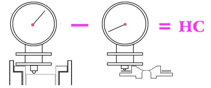
 Now you are ready to measure the head clearance. Our method will be to measure the space between the flange of the liner and the top of the piston at
TDC, and how far the head extends into this space. A simple subtraction will then yield the desired result. You are free to choose whatever instruments
you may have at your disposal for making these measurements. If one is availabe, a depth micrometer is a good choice. Whatever your choice, it is
desirable to have a precision of around 0.02 mm (0.0008") or better.
Now you are ready to measure the head clearance. Our method will be to measure the space between the flange of the liner and the top of the piston at
TDC, and how far the head extends into this space. A simple subtraction will then yield the desired result. You are free to choose whatever instruments
you may have at your disposal for making these measurements. If one is availabe, a depth micrometer is a good choice. Whatever your choice, it is
desirable to have a precision of around 0.02 mm (0.0008") or better.